Next: 6.7 Thermal, chemical, and Up: 6. Wellbore Stability Previous: 6.5 The mud window Contents
The following subsections present a guide for calculating stresses at the wall of deviated wellbores and identifying stress magnitudes and locations for shear failure (breakouts) and tensile fractures.
At any point along the trajectory of a deviated wellbore, the tangent orientation permits defining wellbore azimuth  and deviation
  (Fig. 6.19).
Azimuth is the angle between the projection of the trajectory on a horizontal plane and the North.
Deviation is the angle between a vertical line and the trajectory line at the point of consideration.
These two variables can be plotted in a half-hemisphere projection plot (stereonet).
Notice that a point in this plot represents just one point along a wellbore trajectory.
Fig. 6.19 shows an example of the full trajectory of a wellbore.
(Fig. 6.19).
Azimuth is the angle between the projection of the trajectory on a horizontal plane and the North.
Deviation is the angle between a vertical line and the trajectory line at the point of consideration.
These two variables can be plotted in a half-hemisphere projection plot (stereonet).
Notice that a point in this plot represents just one point along a wellbore trajectory.
Fig. 6.19 shows an example of the full trajectory of a wellbore.
![\includegraphics[scale=0.45]{.././Figures/split/7-DevSurvey.pdf}](img975.svg) |
A given state of stress will result in different mud windows and locations of rock failure depending on the wellbore orientation. Breakouts and tensile fractures will depend on the stresses on the plane perpendicular to the wellbore. Figure 6.20 shows an example for normal faulting with generic stress magnitude values.
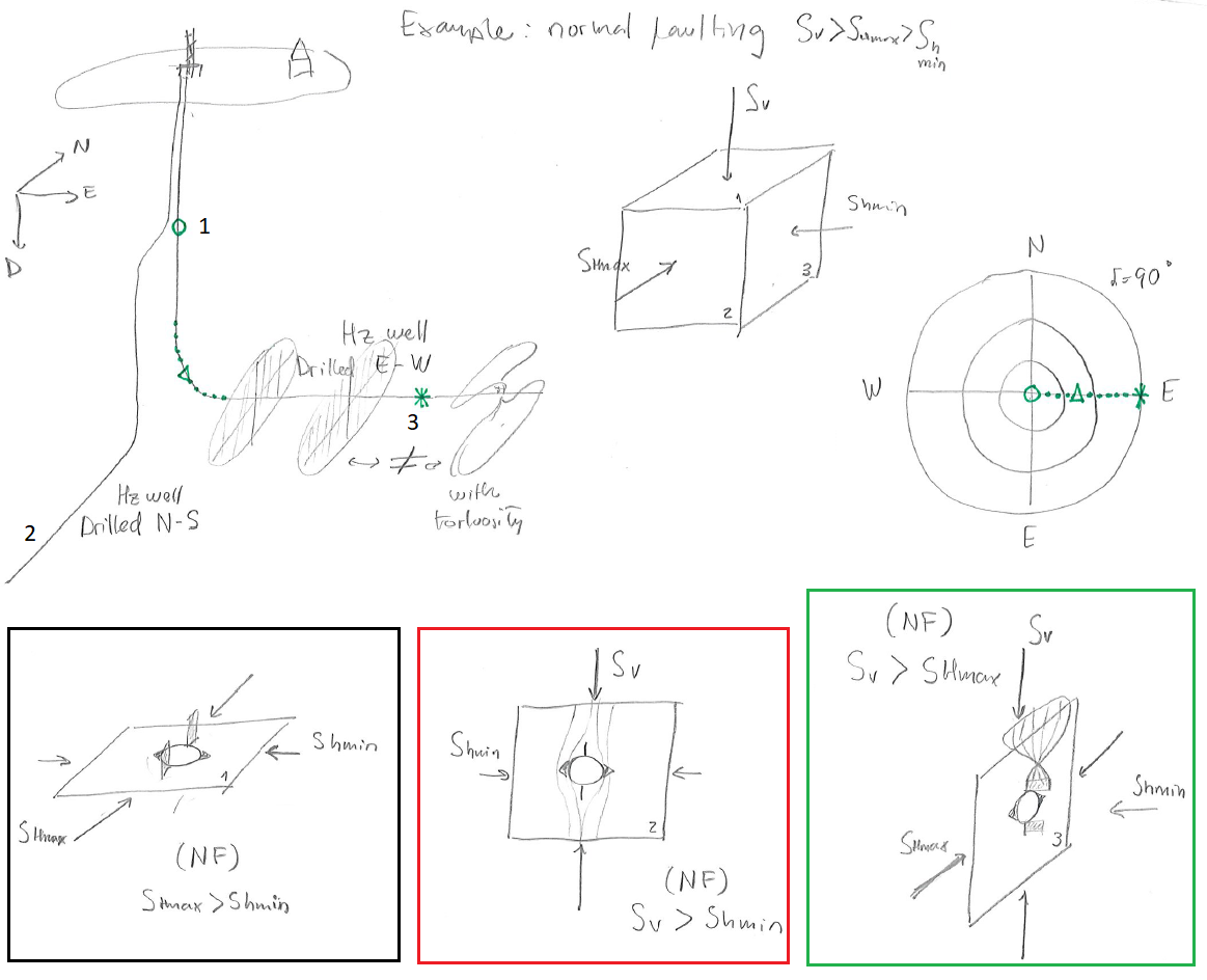 |
PROBLEM 6.4: Consider a place where vertical stress  is a principal stress and the maximum horizontal stress acts in E-W direction.
SOLUTION
The solution below shows just one of the possible solutions of two horizontal wells.
![\includegraphics[scale=0.55]{.././Figures/split/8-ExampleDevWells.pdf}](img976.svg)
Let us define a coordinate system for a point along the trajectory of a deviated wellbore.
The first element  of the cartesian base goes from the center of a cross-section of the wellbore at a given depth to the deepest point around the cross-section (perpendicular to the axis).
The second element of the base
of the cartesian base goes from the center of a cross-section of the wellbore at a given depth to the deepest point around the cross-section (perpendicular to the axis).
The second element of the base  goes from the center to the side on a horizontal plane.
The third element of the base
goes from the center to the side on a horizontal plane.
The third element of the base  goes along the direction of the wellbore.
Based on the previous definition, it is possible to construct a transformation matrix
 that links the geographical coordinate system and the wellbore coordinate system.
Furthermore, the wellbore stresses can be calculated from the principal stress tensor according with:
 |
(6.20) |
Where
 and
and  are the principal stress tensor and the corresponding change of coordinate matrix to the geographical coordinate system (Eq. 5.7).
The tensor
are the principal stress tensor and the corresponding change of coordinate matrix to the geographical coordinate system (Eq. 5.7).
The tensor
 is composed by the following stresses:
![\begin{displaymath}\uuline{S}{}_W =
\left[
\begin{array}{ccc}
S_{11} & S_{12} & ...
...2} & S_{23} \\
S_{31} & S_{32} & S_{33} \\
\end{array}\right]\end{displaymath}](img985.svg) |
(6.21) |
Stresses on the plane of the cross-section of the deviated wellbore at the wellbore wall
 depend on far-field stresses
 ,
,
 ,
,
 ,
,
 ,
,
 , and
, and
 .
The Kirsch equations require additional far field shear terms
.
The Kirsch equations require additional far field shear terms
 ,
,
 , and
, and
 in order to account for principal stresses not coinciding with the wellbore orientation.
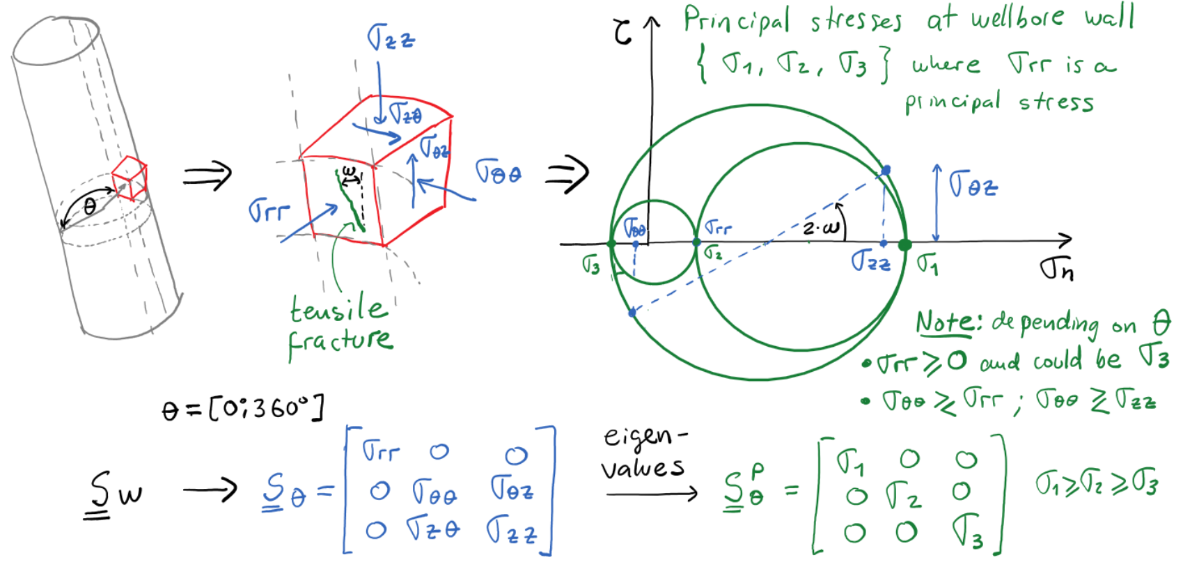
The solution of Kirsch equation for isotropic rock with far-field shear stresses is provided in Fig. 6.22.
in order to account for principal stresses not coinciding with the wellbore orientation.
The solution of Kirsch equation for isotropic rock with far-field shear stresses is provided in Fig. 6.22.
![\includegraphics[scale=0.65]{.././Figures/split/8-3.pdf}](img996.svg) |
Solving for the local principal stresses
 on the wellbore wall permits checking for rock failure (tensile or shear).
The local principal stresses may not be necessarily aligned with the wellbore axis leading to an angle
on the wellbore wall permits checking for rock failure (tensile or shear).
The local principal stresses may not be necessarily aligned with the wellbore axis leading to an angle  (see Fig. 6.23).
Because of such angle, tensile fractures in deviated wellbores can occur at an angle from the axis of the wellbore and appear as a series of short inclined (en-échelon) fractures instead of a long tensile fracture parallel to the wellbore axis as in Fig. 6.16.
(see Fig. 6.23).
Because of such angle, tensile fractures in deviated wellbores can occur at an angle from the axis of the wellbore and appear as a series of short inclined (en-échelon) fractures instead of a long tensile fracture parallel to the wellbore axis as in Fig. 6.16.
 |
Consider a place subjected to strike-slip stress regime with  oriented at an azimuth of 070
 with known values of principal stresses (Fig 6.24).
The maximum stress anisotropy lies in a plane that contains
with known values of principal stresses (Fig 6.24).
The maximum stress anisotropy lies in a plane that contains
 and
and
 , a plane perpendicular to the axis of a vertical wellbore.
Hence, maximum stress amplification at the wellbore wall will happen for a vertical wellbore.
The minimum stress anisotropy lies in a plane that contains
, a plane perpendicular to the axis of a vertical wellbore.
Hence, maximum stress amplification at the wellbore wall will happen for a vertical wellbore.
The minimum stress anisotropy lies in a plane that contains
 and
, perpendicular to a horizontal wellbore drilled in direction of .
Given a mud pressure and a fixed friction angle, we can calculate for a given wellbore orientation the stresses on the wellbore wall from equations in Fig. 6.23, and the required
and
, perpendicular to a horizontal wellbore drilled in direction of .
Given a mud pressure and a fixed friction angle, we can calculate for a given wellbore orientation the stresses on the wellbore wall from equations in Fig. 6.23, and the required  (using a shear failure criterion
 ) to avert shear failure.
The plots in Fig. 6.24 are examples of this calculation.
The maximum value of required corresponds to the wellbore direction with maximum stress anisotropy (vertical wellbore - red region), and the minimum value of required corresponds to the wellbore direction with minimum stress anisotropy (horizontal wellbore with
) to avert shear failure.
The plots in Fig. 6.24 are examples of this calculation.
The maximum value of required corresponds to the wellbore direction with maximum stress anisotropy (vertical wellbore - red region), and the minimum value of required corresponds to the wellbore direction with minimum stress anisotropy (horizontal wellbore with
 - blue region).
Following the breakout concepts discussed before, we would expect breakouts at 160 and 340 of azimuth on the sides of a vertical wellbore.
A horizontal wellbore drilled in the direction of
- blue region).
Following the breakout concepts discussed before, we would expect breakouts at 160 and 340 of azimuth on the sides of a vertical wellbore.
A horizontal wellbore drilled in the direction of  would tend to develop breakouts on the top and bottom of the wellbore.
![\includegraphics[scale=0.70]{.././Figures/split/8-BreakoutsDevWells.pdf}](img1001.svg) |
PROBLEM 6.5: Consider a place with principal stresses  MPa,
MPa,
 MPa (at 070),
 MPa,
MPa,  MPa, and
  MPa. Calculate the required UCS using the Coulomb failure criterion (with
 ) for all possible wellbore orientations.
Plot results in a stereonet projection.
) for all possible wellbore orientations.
Plot results in a stereonet projection.
SOLUTION
![\includegraphics[scale=0.70]{.././Figures/split/8-BreakoutsDevWells-EXNF.pdf}](img1008.svg)
PROBLEM 6.6: Consider a place with principal stresses MPa,
 MPa (at 070),
 MPa, MPa, and MPa. Calculate the required UCS using the Coulomb failure criterion (with
) for all possible wellbore orientations.
Plot results in a stereonet projection.
MPa, MPa, and MPa. Calculate the required UCS using the Coulomb failure criterion (with
) for all possible wellbore orientations.
Plot results in a stereonet projection.
SOLUTION
![\includegraphics[scale=0.70]{.././Figures/split/8-BreakoutsDevWells-EXRF.pdf}](img1011.svg)
The procedure to find tensile failure is equivalent to the one used for shear failure, but using a tensile strength failure criterion.
For example, consider a place subjected to normal faulting stress regime with oriented at an azimuth of 070 and known values of principal stresses (Fig. 6.25).
The maximum stress anisotropy lies in a plane that contains
 and
, perpendicular to a horizontal wellbore drilled in the direction of .
For a given rock tensile strength, we can calculate the maximum mud pressure that the wellbore can bear without failing in tension.
Fig. 6.25 shows an example of this calculation.
The maximum possible
and
, perpendicular to a horizontal wellbore drilled in the direction of .
For a given rock tensile strength, we can calculate the maximum mud pressure that the wellbore can bear without failing in tension.
Fig. 6.25 shows an example of this calculation.
The maximum possible  corresponds to the wellbore direction with minimum stress anisotropy (blue region), and the minimum possible corresponds to the wellbore direction with maximum stress anisotropy (red region).
For example, tensile fractures would tend to occur in the top and bottom of a horizontal wellbore drilled in the direction of .
corresponds to the wellbore direction with minimum stress anisotropy (blue region), and the minimum possible corresponds to the wellbore direction with maximum stress anisotropy (red region).
For example, tensile fractures would tend to occur in the top and bottom of a horizontal wellbore drilled in the direction of .
![\includegraphics[scale=0.65]{.././Figures/split/8-TensfracsDevWells.pdf}](img1013.svg) |
PROBLEM 6.7: Consider a place with principal stresses MPa,
MPa (at 070),
 MPa, and MPa.
Calculate the maximum wellbore pressure at the limit of tensile strength with
MPa, and MPa.
Calculate the maximum wellbore pressure at the limit of tensile strength with  MPa) for all possible wellbore orientations.
Plot results in a stereonet projection.
MPa) for all possible wellbore orientations.
Plot results in a stereonet projection.
SOLUTION
TBD
PROBLEM 6.8: Consider a place with principal stresses MPa,
MPa (at 070),
MPa, and MPa.
Calculate the maximum wellbore pressure at the limit of tensile strength with MPa) for all possible wellbore orientations.
Plot results in a stereonet projection.
SOLUTION
TBD
![\includegraphics[scale=0.65]{.././Figures/split/8-WellCoordSystem.pdf}](img980.svg)


