Next: Determination of horizontal stresses Up: Applications Previous: Applications Contents
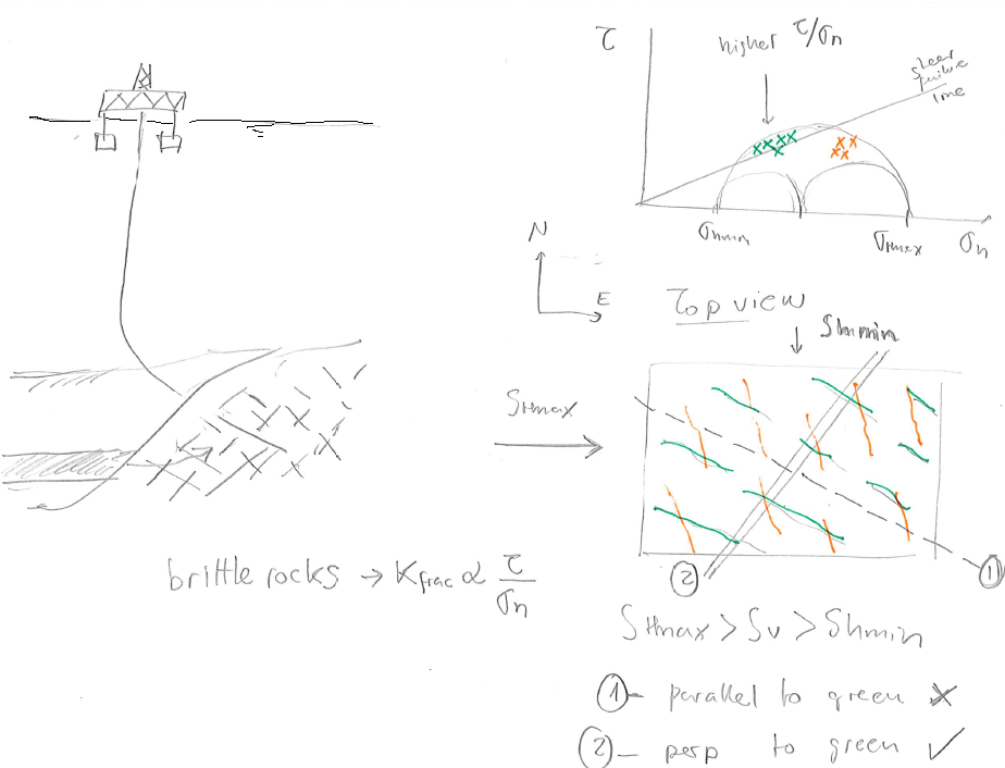
A critically-stressed fracture or fault has a ratio between shear stress and normal effective stress
 which approaches the friction angle
  0.6-1.0.
The fracture is said to be “critically stressed” because it is practically failing (although slowly).
Such fractures -if exhibit dilation during sliding- tend to be more hydraulically conductive than (1) fractures with low
ratio (on the right of the Mohr circle), and (2) fractures with even lower
0.6-1.0.
The fracture is said to be “critically stressed” because it is practically failing (although slowly).
Such fractures -if exhibit dilation during sliding- tend to be more hydraulically conductive than (1) fractures with low
ratio (on the right of the Mohr circle), and (2) fractures with even lower  but negligible
  (points in the far left of the Mohr circle) 5.22.
The concept of critically stressed fractures adds one more level of dependency to the well known dependence of fracture permeability as a function of normal effective stress.
(points in the far left of the Mohr circle) 5.22.
The concept of critically stressed fractures adds one more level of dependency to the well known dependence of fracture permeability as a function of normal effective stress.
![\includegraphics[scale=0.65]{.././Figures/split/6-67.pdf}](img626.svg) |
Hence, the state of stress determines which fractures are hydraulically conductive and also determines permeability anisotropy in a fractured reservoir.
The same reasoning applies to large faults.
There are faults that may be more easily reactivated due to pore pressure changes because of their orientation respect to the current state of stress.
Fractures that have an orientation that favors high
ratio are said to be “critically oriented”.
[make figure example and corresponding assignment with wellbore placement]
Natural fractures can help fluid drainage. Usually fractures have a permeability that depends on the state of stress, where critically oriented fractures have higher permeability than non-critically oriented fractures. The orientation of such fractures is critical for determining the orientation of a horizontal wellbore that minimizes the least resistance path of fluids from the rock matrix to the wellbore. See example in Fig. 5.23.
 |
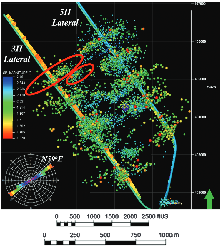
Fractures can also create and reactivate during hydraulic fracturing. The dots in Fig. 5.24 indicate micro-to-nano earthquakes hypocenters (at depth) triggered by rock failure during hydraulic fracturing. Hydraulic fracturing imparts changes of stresses that reactivate some critically oriented fractures in tight reservoirs. These reactivated fractures are useful to contribute to increase the permeability of tight reservoirs at the large scale (also known as Stimulated Reservoir Volume SRV). Some of these created fractures may close and seal-off fairly quickly upon depletion if not propped. Significant ongoing research addresses how to maintain the permeability of these fractures in the long-term.
 |

