Next: 7. Final Project Up: 6. Mechanics of fluid Previous: 6.3 Hydraulic fracturing in Contents
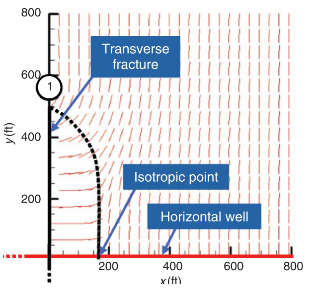
Read the paper “Roussel, N. P., and Sharma, M. M. (2011). Optimizing fracture spacing and sequencing in horizontal-well fracturing. SPE Production and Operations, 26(02), 173-184.” https://doi.org/10.2118/127986-PA.
 .
.
A single hydraulic fracture treatment will be performed in a tight sandstone.
The hydraulic fracture height is expected to be  = 170 ft.
The tight sandstone has a plane-strain modulus
= 170 ft.
The tight sandstone has a plane-strain modulus
 psi.
The (two-wing) injection rate will be 50 bbl/min (constant) during 1 hour.
psi.
The (two-wing) injection rate will be 50 bbl/min (constant) during 1 hour.
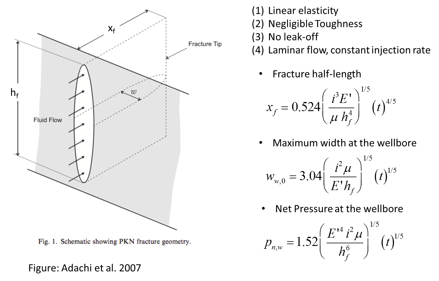
Compute:
 , fracture width at the wellbore
  , and net pressure
  as a function of time with the PKN model (no leak-off) assuming the fracturing fluid has a (constant) viscosity 2 cP.
, fracture width at the wellbore , and net pressure
as a function of time with the PKN model (no leak-off) assuming the fracturing fluid has a (constant) viscosity 2 cP.
, fracture width at the wellbore , and net pressure  as a function of time with the PKN model (no leak-off). Now the fracturing fluid has a viscosity 2 cP with no proppant (initial 10 min), and increases in steps of 10 min with 2 cP in each step (due to increasing proppant concentration).
, , and .
as a function of time with the PKN model (no leak-off). Now the fracturing fluid has a viscosity 2 cP with no proppant (initial 10 min), and increases in steps of 10 min with 2 cP in each step (due to increasing proppant concentration).
, , and .
Hint: convert all quantities to the SI system first